

Sección C: Ingenierías
Methods for conceptual and preliminary seismic design of buildings with steel structure
Métodos para el diseño sísmico conceptual y preliminar de edificios con estructura de acero
ACI Avances en Ciencias e Ingenierías
Universidad San Francisco de Quito, Ecuador
ISSN: 1390-5384
ISSN-e: 2528-7788
Periodicity: Bianual
vol. 11, no. 2, 2018
Received: 25 December 2018
Accepted: 28 February 2019
Corresponding author: tiago.ribeiro@talprojecto.pt

Abstract:
Throughout the last two decades, seismic design standards evolved to ever more comprehensive and detailed prescriptions, stressing out the need for design methods that deal with earthquake effects not as actions, but as a design philosophy. The Eurocode 8 adoption as national law throughout the European Union countries and informally in many parts of Africa, Asia and Latin America is the pretext for the current study. It aims to provide some guidance to the seismic design of steel structures as well as to the Eurocode 8 implementation by the designers. Some lines on the preliminary design of structural systems were written based on several real cases of structures designed taking into account the seismic action. Such a content is, usually, relevant in any design guide, given its value in enhancing the design technical and economical content. However, it is now of utter significance at the current context as an essential tool to facilitate the safety checking of several code requirements.
Keywords: Seismic Design, Steel Structures, Eurocode 8, Conceptual Design, Steel Connections.
Resumen:
A lo largo de las últimas dos décadas, los estándares de diseño sísmico evolucionaron a prescripciones cada vez más completas y detalladas, destacando la necesidad de métodos de diseño que traten los efectos de terremotos no como acciones, sino como una filosofía de diseño. La adopción del Eurocódigo 8 como ley nacional en todos los países de la Unión Europea e informalmente en muchas partes de África, Asia y América Latina es el pretexto del estudio actual. Su objetivo es proporcionar cierta orientación al diseño sísmico de estructuras de acero, así como a la implementación del Eurocódigo 8 por parte de los proyectistas. Algunas líneas en el diseño preliminar de sistemas estructurales se escribieron basándose en varios casos reales de estructuras diseñadas teniendo en cuenta la acción sísmica. Tal contenido es, generalmente, relevante en cualquier guía de diseño, dado su valor para mejorar el contenido técnico y económico del diseño. Sin embargo, ahora es de suma importancia en el contexto actual como una herramienta esencial para facilitar la verificación de seguridad de varios requisitos del código.
Palabras clave: Diseño sísmico, estructuras de acero, Eurocódigo 8, diseño conceptual, conexiones de acero.
INTRODUCTION
The state-of-the-art of structural design can be rather distant from the latest research developments. That is particularly true for the seismic design of common building structures, whose procedures respect the design codes prescriptions but usually do not go beyond them nor tend to allow any innovative solutions. However, when the design code is new and it comes with less simplified theoretical concepts and practical rules, it becomes clear that time will be needed for the common designers to adapt to the new ways, as well as some sound guidebooks will be needed to explain the code and facilitate the code implementation. That is what has been happening throughout Europe with the introduction of the Eurocodes (namely the Eurocode 8 as seismic code) as national standards, and that is why this work is expected to give its small contribution to designers, helping them to understand the code and to researchers, helping them to understand the practical problems resulting from the code application.
The choice of buildings with steel structures for this study results from the fact that a lot of design guidebooks and papers have been written on the seismic design of reinforced concrete structures to the Eurocode 8 (many of them with excellent quality) but much less has been written on the same subject for steel structures, apart from some noteworthy exceptions such as (Landolfo et al., 2017). This is can be regarded as peculiar, once the steel structures have unique capabilities to bear efficiently the seismic actions.
The steel structure advantages for seismic design can be summarized into four main features. Those are: (i) the material high ductility (steel sections undergo drastic plastic deformations, enabling notorious strains without losing its resistance, and unlike the in-situ casted materials, there is a great reliability in this property, as the material is industrially manufactured), (ii) the decreased construction weight, (iii) the structural flexibility (given by steel structural systems high resistance despite the greatly variable structural outfits) and (iv) the system reparability (by reducing the plastic deformation and damage to certain zones or elements where the system reparability is made possible and much more affordable than for other structural materials).
As no structural system or material can be proclaimed ideal for seismic design, the message carried by this work is that the technical and economic efficiency can only be attained by a broad comparison of very different solutions at an early stage. Discarding the already well-studied concrete seismic design, special attention is paid to the steel systems. Those can present very interesting solutions for certain cases, but one should attend to the fact that its design can be more complex – with more interrelated code prescriptions – fundamentally because resistance, lateral stiffness and seismic load are very interconnected, once unlike with some other materials it is nearly impossible to modify resistance without changing the stiffness.
STRUCTURAL SYSTEMS ADEQUACY AND PRELIMINARY SEISMIC DESIGN
From the lateral load bearing system, the typical building steel structures can be concisely divided into Moment Resisting Frames, Frame with Eccentric Bracings, Frame with V Concentric Bracings, Frame with Diagonal Bracings, Frame with X Concentric Bracings, Dual Systems with more than one of the latter or with any of them and Reinforced Concrete Frames or Walls. To the preliminary design purpose, some less common systems such as Inverted Pendulum, Trussed Frames, Frames with Buckling Restrained Braces, Base Isolated and Systems with Supplementary Damping Devices are left behind, as its design is very specific and therefore unable to be described in such a general manner.
The structural system choice shall be driven by the adequacy to the imposed horizontal loads in such a way that a balanced dynamic behaviour is achieved, as well as the safety checking to the several code prescribed limit states. Assuming the usual geometries and material quantities, the list at Table 1 is ordered in increasing stiffness. Except for the structural systems involving reinforced concrete parts, whose study must be done in parallel with the structural steel system at an early stage, in order to assess which one is the most efficient, the structural type shall be defined to suit the structural stiffness to the design horizontal loads. In this manner, as more intense the seismic action is and taller and heavier the building, stiffer must be the structural system in order to comply with lateral displacement requirements. However, it is important not to choose a system that is too stiff, once it will undergo higher internal forces and accelerations, what may become to difficult to handle within the normative requirements. Furthermore, throughout the design and safety checking procedures it will be much easier to stiffen the structure than soften it, once the later implies moving towards a more flexible structure while needing it to be more resistant (the resistance is, usually, achieved iteratively in order to keep the design economically efficient), which is rather difficult when, for steel structures, resistance and stiffness are very interconnected.
When the concrete walls are mixed with the steel structure, it is common that given its larger stiffness (which is usually greater than for the steel stiffer system) those walls will become the primary structural systems, absorbing the major part of the imposed seismic forces what will lead to its further increase in size and stiffness, leaving the steel structure in a secondary role. The conjunction of concrete and steel systems makes only sense to correct the structural deformed shape, in such a way that the interstorey drifts are limited without stiffening too much the structure to avoid greater seismic forces.
Keeping in mind that the seismic action is highly dependent on the structural system and that, therefore, the design (even the preliminary phase) and the limit state safety checking are interrelated and very iterative, it is easy to realize that an excellent preliminary design is the stepping stone to carry out a smooth design process. One design without the need for a dramatic structural change at an advance design stage, while carrying out all the code prescriptions till the connections design.
Based on the analysis of major seismic code prescriptions (mainly the Eurocode 8, but also some American, Romanian and Japanese codes) as well as several real cases (designed and built in Portugal and Romania, some discussed in (Ribeiro & Abecasis, 2009), (Ribeiro & Abecasis, 2009a), (Ribeiro, 2017) and (Dubina, Dinu & Stratan, 2017)), a short table was composed to help the designer with the decision of what structural system to choose. The information used as input to this table relates only to common building structures, disregarded the mixed use of more than one structural system, as it leads to potentially very heterogeneous outcomes, and so, its output is a merely indicative guidance that shall not be regarded as definitive criteria neither used beyond the conditions of the input information.
Table 1 Guidance on the structural types for the preliminary design
| Moment Resisting Frames | Adequate (generally restricted by the interstorey drift sensitivity coefficient) | Less Adequate (too flexible) | Less Adequate (too flexible) | Inadequate |
| Frame with Eccentric Bracings | Adequate | Adequate | Adequate (generally restricted by the links resistance) | Less Adequate (generally restricted by the links resistance or by the ULS safety checking) |
| Frame with Concentric Bracings | Less Adequate (stiffer and less dissipative) | Adequate | Adequate | Adequate (generally restricted by the SLS, may not be the most cost-efficient solution) |
| Reinforced Concrete Walls with Steel Frames | Less Adequate (too stiff, possibly to onerous) | Adequate | Adequate (generally restricted by the ULS safety checking) | Adequate (generally restricted by the SLS safety checking) |
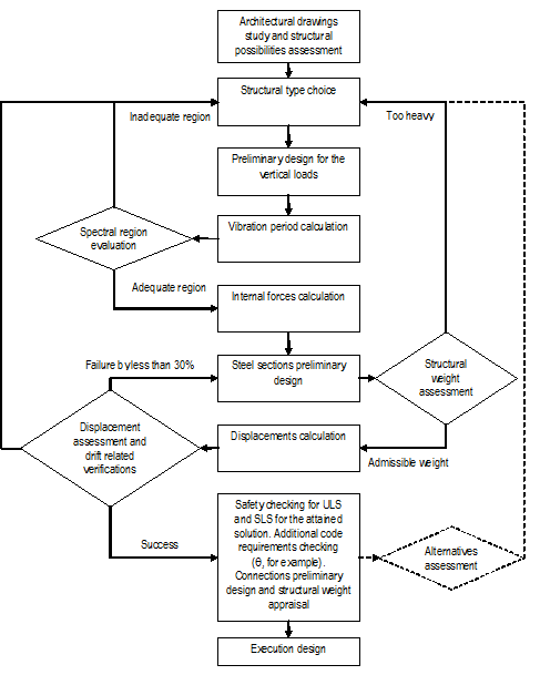
The proposed procedure for the preliminary seismic design of a steel structure includes the following steps:
i) After having preliminarily designed the structure for the gravity loads (slabs, beams and columns), the designer needs to choose the horizontal load bearing structural type. The desired lateral stiffness, the action intensity, the building mass and height, as well as the architectonical and constructive restrictions shall be taken into consideration.
ii) To assess, with simple calculations, the first vibration mode shapes and periods in order to find the most suitable system stiffness considering the design spectral shape. To that end, several simple expressions are widespread in the literature. However, the expressions which do not take into account the major variables (structural mass, height and stiffness) as for example the ones that only consider the height or number of storeys, shall be discarded because their validity is restrained for certain types of structures, what is usually unknown by the regular user. Special attention shall be paid to the effects of the foundation system (consulting relevant bibliography such as (Durante et al., 2015) and (Elnashai & Di Sarno, 2008)), cracking of concrete parts and masonry infills (or any other rigid non-structural elements) on the system dynamic behaviour. Beyond applying some corrective factors to the simplified equations, a range of results shall be used instead of a single value in this early stage.
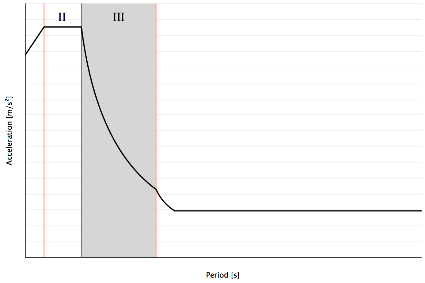
Taking into consideration the Eurocode 8 design spectra (that is very similar to the code spectra defined in most current seismic codes around the world), one can observe that, in order to attain an efficient design, the main vibration modes (usually 2 to 3 in each relevant direction) shall be contained into the third spectral region (III), where the spectral velocity is constant. By doing so, the designer will attain a structural outfit where the seismic induced internal forces will be much lower than the ones that would result from having the main modes in region II (constant acceleration), while the lateral displacement will be manageable (by stiffening the structure or otherwise within the constant velocity region is possible to change the lateral displacements efficiently). On the other hand, a more flexible structure that fits into the fourth region is very likely to have serious lateral displacement problems that might be very difficult to overcome, once that region is characterized by the spectral constant displacement.
It is worth saying that locating the structural period into the constant velocity zone can be difficult for some code defined spectra. For instance, this region is defined between 0,5 s and 5 s for some American codes, but for the Eurocode 8 this range can be as narrow as 1,2 s (between 0,8 s and 2,0 s), what makes the structural system definition much grimmer.
In order to proceed with these simplified preliminary design procedures it is important that the attained structural configuration proves itself balanced. This means that having a torsionally flexible structure or one with an uneven displacement, beyond promoting an undesired behaviour it requests computational analysis since the earliest stage instead of using these instinctive procedures.
iii) To compute the internal forces, affected by the behaviour factor. For this purpose the seismic load can be simplified into a triangular shaped diagram. The linear, uninterrupted structural systems can be considered as cantilevers with trussed or Vierendeel behaviour and an effective mass reduction is due to the effected of higher order vibrating modes.
Despite being quite easy to compute the internal forces both for trussed or Vierendeel cantilevers, it is suggested that for the later, that may seem more demanding, a Principle of Virtual Work based expression is used. Therefore, the bending moments in beams (Mpl,beam) and columns (Mpl,column) may be computed as V x ∑ z.. / ∑ z. = n. x Mpl,beam + n. x Mpl,column, where V is the base shear, n. and n. are the number of plastic hinges in beams and columns and z is the storey height.
For flexible and ductile structural systems, as Moment Resisting Frames, it is proposed to leave the internal forces analysis (explained at this point) as well as the U.L.S. resistance safety checking to be done after the displacement calculation (at iv)) and the interstorey drift sensitivity coefficient checking, once it is most likely that a reduced behaviour factor will be required for this displacement checking. The sectional resistance is likely to be less of a problem. In this manner, the most efficient solution is attained much more rapidly.
iv) To assess the lateral displacements and the deformed shape of the structure. The top displacement for the U.L.S. seismic action can be an effective tool to control the system flexibility, while seizing the material ductility. By setting a desired top displacement (for example 2%) and checking the deformed shape one can avoid undesired interstorey drifts without turning the structural system into a unnecessarily stiff one.
The displacements may be computed directly through the displacement spectra or based on the previously calculated shear force. In both cases some aspects need to be addressed. Among them are the fact that the design spectra produces results for a SDOF system while the period simple calculations were made considering a MDOF system and the effect of the higher order modes into the structural behaviour. Considering these effects, it is suggested to compute the structure’s top displacement based on the acceleration spectra as dtop = S. x c x T. / 4π. with c of approximately 1,80 (varying in a range of 1,50 for taller structures to 1,95 for lower ones). The shear deformation shall also be accounted for.
No less important is the evaluation of the second order effects due to the seismic displacement, as well as of the interstorey drift. In order to check those parameters one shall account for the structure deformed shape. For instance, a cantilever like structural system, loaded with an inverted triangular shaped action has the maximum interstorey drift of dstorey = p x H. / (120 x E x I) x (11 – 20 x a. + 10 x a. – a.) with a = (H – h) / H where H is total height, h the last storey height, E is the material Young modulus, I the inertia and p the maximum seismic load in kN/m.
It goes without saying that all the previous force and displacement results shall be directionally combined. The simplest and yet reliable way of doing so is summing the results in each direction with 30% of the values attained at its orthogonal direction (as allowed in EC8).
v) To perform some of the code main safety checks for the structure as a whole and for the most numerous and more stressed sections. The connections design shall not be forgotten, once unfeasible connections will jeopardize the whole structural behaviour.
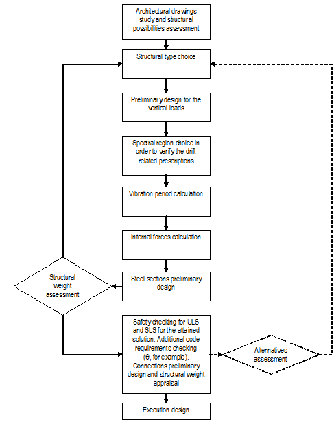
For more experienced designers this sequence can be cut short and tailored in order to attain the most adequate design, from the earliest stage. In order to doing so it is requested a clear initial knowledge of what the structural system shall look like. The process initiates with the choice of a target spectra region (constant velocity) and a target top displacement. Then, the SDOF period may be computed as T = 2π x S. / S.. Subsequently, the MDOF period is attained and, therefore, the system desired inertia may be calculated. The structure is defined and the remaining analysis and safety checking may be performed. The next schemes illustrate the two approaches.
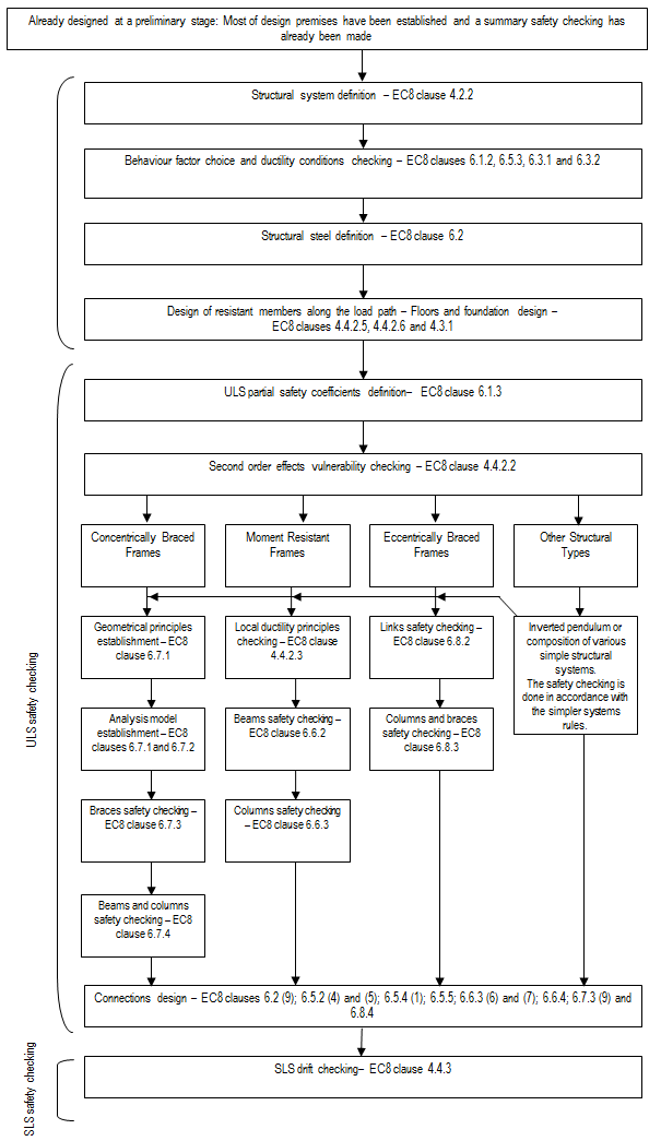
FROM EUROCODE 8 TO THE DESIGN GUIDANCE. PROPOSED PROCEDURES AND SOLUTIONS
Even if it is not possible to compress a design guide into a paper, the general outlook can certainly be given through the exposing of the major steps. For that purpose, the graphic representation has been chosen.
Within these steps many procedures can be taken. One of those is the Improved Force Based Design method (IFBD (Castro, Villani & Elghazouli, 2009), (Peres, Castro & Bento, 2016)) that, even if demanding a slight reordering of the fist steps, can be very useful for the design of Moment Resisting Frames in medium seismicity zones or in low to medium rise buildings, where EC8 (EN 1998–1, 2004) clause 4.4.2.2 is the main design restriction if the maximum allowed behaviour factor is used.
One serious issue is the code prescription, at clause 6.5.4 (1), deemed to assure the plastic hinge development in tension loaded members without early rupture. This prescription makes sense, but given the EN1993-1-1 (EN 1993-1-1, 2005) safety partial factors and yield and ultimate stresses for the common structural steels, leads to the conclusion that no holes can be made in most profiles, making very difficult to design bolted connections.
Considering the code expression Npl,Rd = A x f. / γM0 < Nu,Rd = 0,9 x Anet x f. / γM2 with γM0 = 1,00 and γM2 = 1,25, one can be guided to the conclusion that the ratio Anet / A, for a S275 steel section less than 40 mm thick cannot be lower than 0,888, for a S355 steel section less than 40 mm thick cannot be lower than 1,006, for a S355 steel section more than 40 mm thick cannot be lower than 0,990 and for a S450 steel section less than 40 mm thick cannot be lower than 1,111. This shows the impossibility of having bolt holes in the tensioned members.
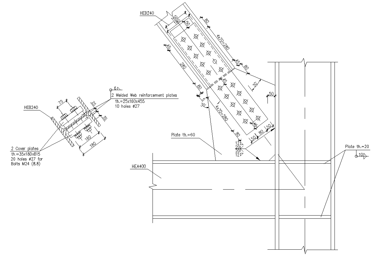
To overcome this problem some strategies can be drawn. The first, and simplest, would be the use of steel grades with higher f./f. ratio, what seems impossible given the definition of these parameters in the Eurocodes. The other strategies would be the quincunx disposal of bolt holes, fading the problems, but not solving them or, reinforcing the connected sections.
This latter appears to be the most efficient and code compliant strategy, once the bolted section reinforcement will enhance largely its yielding capacity, allowing the plastic hinge formation in an integer section. The following figure shows one connection with reinforced bolted webs and quincunx disposal of bolts.
ON EUROCODE 8 POSSIBLE FURTHER DEVELOPMENTS
There are no timeless design codes, and Eurocode 8 is not an exception. Furthermore, prescribing tangible procedures, methods and expressions beyond the abstract principles of adequate mechanical behaviour and design philosophy makes this code very prone to inconsistency among prescriptions, turning it, as well, into an out-of-date document very rapidly.
Leaving out of this work the long discussion on the design philosophy review that must be done to set path to future code developments, it is important to highlight some practical aspects that deserve prompt review. The aim of this suggestions is to contribute to a more unambiguous and user-friendly code, that can be understood and applied by the practitioners, leading to the structural safety but not to design impossibilities. Some of these suggestions can be found on the next table. Some of the adreesed issues are also discussed in (Castro, Elghazouli & Izzuddin, 2008), (Elghazouli, 2009), (Elghazouli, 2009a) and (Ribeiro, 2017). Further developments can be found in (Silva et al., 2018) and (Costanzo, D’Aniello & Landolfo, 2019).
| Clauses | Suggestion |
| 2.1, 2.2.3 and 4.4.3 | Currently, the Eurocode 8 prescribes an unique serviceability criteria, in the form of an interstorey drift limitation, deemed to satisfy the damage limitation and avoid disproportionate repair costs. However, not only the interstorey drift may be not entirely related with the repair costs, but, as a very strict requirement has been settled, it is very common that the entire structural design is driven by this requirement, in a way that the structural system “improvement” to respect this requirement means an increase in the costs greater than the repair cost that it is deemed to avoid and a stiffer behaviour, making it more susceptible of undergoing severe seismic accelerations and internal forces. In this manner it is suggested that this interstorey drift requirement is substituted by the requirement of studying the expected repair costs for the serviceability actions, and only after comparison with the structural system initial cost and upon agreement with the Owner/Investor to settle drift limitations or guarantee displacement capacities without meaningful damage both in structural and non-structural elements. |
| 2.1, 2.2.3 and 4.4.3 | Instead of using a linear reduction of the ULS design spectra for the SLS spectra, it is suggested that this performance requirement is provided with its own spectra, taking into account the intrinsic characteristics of a lower PGA event and avoiding the ULS minimum acceleration threshold that is the cause of large code defined displacements in flexible structures. |
| 2.1 and 2.2.3 | Among the serviceability requirements it is suggested to consider the structural acceleration limitation, as a way to prevent the casualties induced by furniture impact occurred for frequent seismic events. |
| 3.2.2.2 | It is suggested that some prescriptions are included in order to enable the assessment of the soil-structure interaction into the damping parameter. |
| 3.2.3 and NA | A list of suitable and scaled accelerograms could be prescribed for the non-linear dynamic analysis. Otherwise, the use of this kind of analysis will be kept inaccessible for the regular designers. |
| 4.2.5 | The importance classes could be defined with concrete parameters beyond its functionality (average occupancy, built area, public ownership, property fiscal value, among others) as way to avoid subjective classifications. |
| 4.2.5 | The built environment and vicinity could be taken into account for the importance classification of a structure. |
| 4.4.2.3 | The prescription that states that the columns bending resistance must be, at least, 30% higher than the beams resistance may need an evaluation. On one hand, some studies have concluded that this value may not be sufficient to guarantee the beams plastic rotation capacity without hinging the columns. On the other hand, the application of this clause to every moment resistant frame system doesn’t exclude the dual systems with bracings and moment frames. This structural system could benefit from adding a less stiff moment frame to a stiffer braced frame, but this prescription may lead the designer to the conclusion that the columns cannot be optimized given such condition. Therefore, some analysis is needed to assess whether the prescription is necessary when the moment frame is not the main (and stiffer) structural system. |
| 6.3.1 and 6.3.2 | The dual or composite structural systems (mixing more than one base systems) are not extensively defined in Eurocode 8. In fact, there are not many prescriptions for structural systems that need to add structural systems such as moment frames with braced frames or any of these with concrete or composite steel-concrete frames or walls. Many times these are the “real” structural systems both for architectural or geometric reasons and for structural convenience. Therefore, the code could provide more comprehensive descriptions on these composite systems, including specific prescriptions and realistic behaviour factors. |
| 6.3.1 (5) | Enlightenment could be provided for the braced structural type composed by V and inverted V braces. It doesn’t seem controversial to say that its behaviour is close to the behaviour of X braces, only with an intermediate beam. However, given the code current descriptions, the system can be regarded as a V braced one, what leads to very different analyses. |
| 6.3.1 (5) and 6.7.3 | Some structural types are absent from the code recognition, most of them cannot be designed according with the prescriptions and behaviour factors proposed for the more conventional ones. Among this group that could be included into the code one can count the Buckling Restrained Braces, the Trussed Moment Resisting Frames or the Self-Centring Systems. |
| 6.3.1 (5) | From the designer point of view it is extremely difficult to guarantee an hinge formation on the columns bottom, given the column base connection geometry that leads to greater moment resistance and stiffness at the column bottom end. However, that hinge is drawn in the Moment Resisting Frame description, even if no further instructions are provided. Therefore, it should be enlightened by the code if this plastic hinge is mandatory or for what type of structure (number of bays and storeys) it is mandatory. If selected as mandatory, some further prescriptions are necessary, such as the hinge possible locations or the prescribed failure modes. If the hinge is neglected, then some further requirements may be imposed, such as the maximum allowed behaviour factor reduction or a minimal requirement for the base connection rotation capacity. |
| 6.5.4 (1) | Whenever there is the guarantee of not having an hinge at the connection zone (along with the prescription of having a non-dissipative connection resistance at least 37,5% greater than the connected member resistance) should be enough to dismiss the need for the connection shear resistance being 20% higher than its bearing resistance. Usually, to comply with 6.5.4 (1) requirement, there is the need for sectional reinforcement, which along with those cumulative prescriptions may lead to unfeasible connection details. |
| 6.5.4 (1) | The allowance for considering steel ultimate stresses higher than what is prescribed at EN10025 and EN1993-1-1, once those values are guaranteed by the manufacturers, would allow this code prescription to be fulfilled without local reinforcement. |
| 6.5.5 (6) and (7), 6.6.4 (2) and 6.7.3 (9) | The current prescription of the need for experimental evidence for the dissipative connections, or connections into dissipative zones, makes it almost impossible for the practitioners to design according to such a philosophy. Even when some experimental evidence is available, it is very difficult to assess if it can be related to certain connection geometry and members size. Therefore, it is suggested that some pre-approved connection types, along with well-defined geometry ranges, are incorporated into the code. |
| 6.5.5 | Some specific information on pinned connections would be useful for the designers to understand if that is an admissible solution (for braces, essentially) once they are not B or C category connecting devices, but clearly different from bolted connections. |
| 6.6.3 (1) | It is suggested that the Ω factor, currently computed in Eurocode 8 as Ωi = Mpl,Rd,i / MEd,i may be changed to Ω = (Mpl,Rd – MEd,G) / MEd,E. |
CONCLUSIONS AND FINAL REMARKS
The four main subjects briefly addressed by this work are:
i) The preliminary design importance. Despite the seismic code to be followed or the employed analysis method, a comprehensive preliminary design is essential to facilitate the structural types comparison and its detailed design.
ii) The Eurocode 8 prescriptions apparent complexity and interrelatedness. Indeed, the normative package of prescriptions becomes too iterative for the regular structural engineer to manage it. The proposed solutions are, firstly the code explanation and theoretical grounding so that its user can understand fully the intent of its prescriptions, than the rules reordering in a way that is consistent with the design sequence and, ultimately, the use of some design methodologies which are coherent with the Eurocode 8 rules but introduce simplicity and linearity into the design process.
iii) The difficulty of satisfying Eurocode 8 requirements with the current structural solutions. For such situations some new approaches are proposed. Even if in some of the cases solutions request further development and experimental evidence, some of them already on-going, it is believed that solutions such the local reinforcement of bolted sections will definitely help the designers to overcome some new difficulties imposed by the Eurocode 8.
iv) The need for improvement and further development of the European code. Some theoretical and practical faults on the Eurocode 8 prescriptions are identified, as well as the way of correcting them. For these cases short term action is suggested, once the code philosophy will not be affected.
REFERENCES
Castro J.; Elghazouli A.; Izzuddin B. (2008) Seismic performance of composite moment-resisting frames, Engineering Structures, Elsevier
Castro J.; Villani A.; Elghazouli A. (2009) Nova metodologia de dimensionamento sísmico de pórticos metálicos, Porto
CEN (2005) EN 1993-1-1, Eurocode 3: Design of steel structures - Part 1.1: General rules and rules for buildings. European Committee for Standardization, Brussels
CEN (2004) EN 1998–1, Eurocode 8: Design of structures for earthquake resistance. Part 1: General rules, seismic actions and rules for buildings. European Committee for Standardization, Brussels
Costanzo S.; D'Aniello M.; Landolfo R. (2019) Proposal of design rules for ductile X-CBFS in the framework of EUROCODE 8, Earthquake Engineering & Structural Dynamics 48(1)
Dubina D.; Dinu F.; Stratan A. (2009) Tower Centre International building in Bucharest – Part I: Structural design, Steel Construction 2(4)
Durante M.; Di Sarno L.; Mylonakis G.; Taylor C.; Simonelli A. (2015) Soil – pile – structure interaction: experimental outcomes from shaking table tests, Earthquake Engng Struct. Dyn
Elghazouli A (2009) Seismic Design of Buildings to Eurocode 8, Spon Press, London
Elghazouli A. (2009a) Assessment of European seismic design procedures for steel framed structures, Bull Earthquake Eng, Springer, London
Elnashai A.; Di Sarno L. (2008) Fundamentals of Earthquake Engineering, Wiley, ISBN: 978-0-470-02483-6
Landolfo R.; Mazzolani F.; Dubina D.; Silva L.; D'Aniello M. (2017) Design of Steel Structures for Buildings in Seismic Areas, ECCS Press / Ernst & Sohn, WileyISBN: 978-3-433-03010-3
Peres R.; Castro J.; Bento R. (2016) An extension of an improved forced based design procedure for 3D steel structures, Steel and Composite Structures, Vol. 22, No. 5
Ribeiro T.; Abecasis T. (2009) Cascade Park Plaza Office Building - Dimensionamento de um edifício alto em zona de elevada sismicidade, VII Congresso de Construção Metálica e Mista, Lisboa
Ribeiro T.; Abecasis T. (2009a) Estudo comparativo de sistemas estruturais para edifícios altos em zonas de elevada sismicidade, VII Congresso de Construção Metálica e Mista, Lisboa
Ribeiro T. (2017) Dimensionamento Sísmico de Edifícios com Estrutura Metálica - Um Manual de Aplicação, OmniScriptum GmbH, ISBN: 978-3-330-99811-7
Silva A.; Santos L.; Ribeiro T.; Castro J. (2018) Improved Seismic Design of Concentrically X-Braced Steel Frames to Eurocode 8, Journal of Earthquake Engineering
Notes
Author notes
tiago.ribeiro@talprojecto.pt